
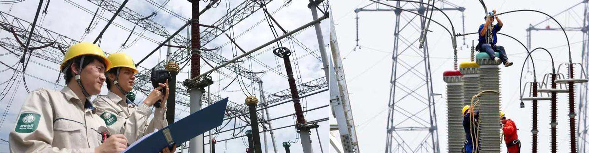
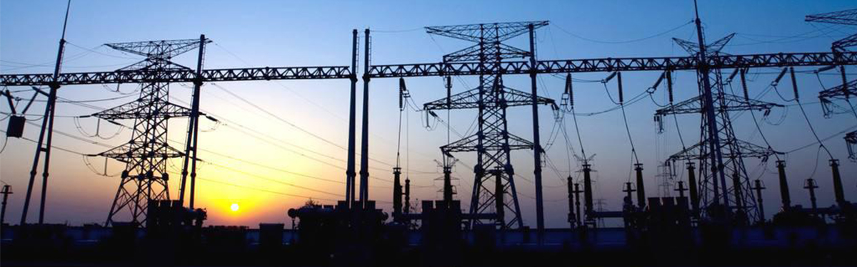
Large ground grid tester in strong electromagnetic environments such as high-voltage substations
The large ground grid tester, often referred to as the large ground grid grounding resistance tester or variable frequency high-current grounding impedance test system, is specialized equipment used in power systems, lightning protection engineering, and large buildings to measure the characteristics of large grounding devices.
Unlike ordinary hand-cranked or simple digital grounding resistance testers, it is specifically designed for large ground grids (such as 500kV substations, power plants, and large communication base stations) and can solve the problem of measuring the impedance of large current grounding systems under strong electromagnetic interference environments.
Here is a detailed explanation of the core principles, functions, and applications of this device:
⚡ Core Pain Point: Why Use a "Large Ground Grid" Tester?
In strong electromagnetic environments such as high-voltage substations, traditional grounding resistance testing methods (such as the power frequency high-current three-pole method) face significant challenges:
Strong power frequency interference: The 50Hz power frequency electromagnetic field generated during grid operation can severely interfere with test signals, causing measurement data fluctuations or even errors.
High current requirements: To suppress interference, traditional regulations require test currents to reach 30A or even higher, making the equipment extremely heavy and wiring difficult.
Concept upgrade: For large ground grids, grounding characteristics exhibit a distinct "complex impedance" nature (including resistance and reactance). Simply measuring "resistance" is no longer accurate; "impedance" must be measured.
⚙️ Working Principle: Heterodyne Anti-Interference Technology
The core technology of the large ground grid tester is the heterodyne method (variable frequency anti-interference technology):
Variable frequency output: The internal high-power variable frequency power supply does not output 50Hz power frequency current but instead outputs sinusoidal currents at specific frequencies such as 45Hz and 55Hz (or within the 40-70Hz range).
Digital filtering: The instrument uses high-precision frequency-selective amplifiers and digital filtering technology (similar to military electronic countermeasure technology) to extract only signals at specific frequencies (e.g., 45Hz/55Hz) and filter out 50Hz power frequency interference signals.
Equivalent calculation: By measuring the impedance at 45Hz and 55Hz, the grounding impedance value at 50Hz power frequency is calculated using algorithms.
This method ensures measurement accuracy while allowing the use of smaller test currents (typically 1A-5A, with some high-power models reaching 50A), greatly reducing on-site workload.
