

When measuring circuit breaker loop resistance on site, a common problem is inconsistent results from multiple measurements of the same equipment, or significant deviations from handover test data. Investigation reveals that in most cases the issue is not a fault in the instrument itself, but rather excessively long current leads, improper placement of voltage clamps, or oxidation of contact surfaces, which cause lead resistance and contact resistance to be included in the measurement. Such errors are particularly pronounced in micro-ohm level measurements and can easily lead to misjudgment of switch contact conditions.
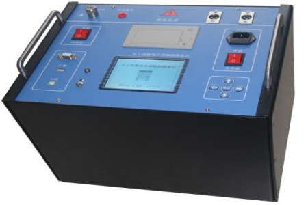
The HLX-150A Loop Resistance Tester employs a four-wire measurement principle, with current and voltage leads independently routed. During on-site operation, the current leads should be as short as possible with sufficient cross-sectional area, and the voltage clamps must be clamped inside the current clamps so that the voltage sampling points are within the current loop, thereby avoiding additional errors introduced by lead resistance and contact resistance. For measurement locations such as disconnector contacts and circuit breaker arc chamber contacts, it is recommended to first remove the oxide layer from the contact surface before clamping the leads to ensure stable contact resistance.
The instrument's testing process is automatically executed by an internal microcontroller, and measurement can be completed with a single key press. The LCD screen displays the resistance value and test current, and supports result printing. Before each test, confirm that the circuit under test has been de-energized and fully discharged, with reliable grounding. After testing, promptly record the ambient temperature and humidity for subsequent horizontal comparison of data. If multiple measurements show large dispersion, priority should be given to checking the wiring position and contact condition rather than repeatedly adjusting instrument parameters.
The instrument is small and lightweight, suitable for on-site carrying, but should be protected from severe vibration and stored away from humid environments. After use, the current and voltage leads should be straightened and coiled, and the clamps should be checked for looseness or corrosion, with timely replacement if poor contact is found. When not in use for extended periods, periodically power on to check the display and key functions to keep the equipment in usable condition. The anti-interference capability and protection functions can handle common electromagnetic environments in substations, but during testing, strong interference sources should still be avoided to ensure stable readings.

