

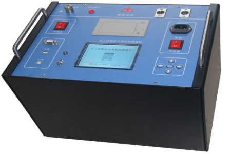
During switchgear handover acceptance or circuit breaker routine maintenance, O&M personnel often need to repeatedly measure contact resistance at moving and fixed contacts, busbar joints, and similar locations. If the same equipment yields significantly different readings on different instruments, the discrepancy is often related to test current magnitude, wiring method, and instrument stability in vibrating environments. The HLC-200B loop resistance tester is designed for such on-site comparison needs, using high-precision resistance elements to reduce the influence of ambient temperature changes on measurement results; the connectors use military-grade specifications to enhance the unit's vibration resistance during transport and on-site operation.
The instrument provides two DC measurement current ranges, greater than 100A and 200A, allowing users to select the appropriate range based on the rated current of the test object and on-site power supply conditions. Measurement accuracy is Class 0.5, suitable for handover tests and preventive tests that require high consistency of contact resistance values. The DC output method helps reduce the influence of test lead inductance, and readings can be recorded once stabilized.
The measurement process and results are displayed on an LCD screen, allowing direct reading of resistance values and test current under on-site lighting conditions. The instrument supports result printing, making it convenient to attach raw data to maintenance records and reducing manual transcription. For switchgear maintenance work that requires retaining multiple measurement point data sets, printed output can serve as a supplement for on-site documentation archiving.
The operating temperature range is -10°C to 50°C, covering the maintenance seasons of most indoor and outdoor substations. The input voltage is AC220V±, and the operating current is designed for AC 220V supply conditions. Before on-site use, confirm power supply capacity and grounding conditions, and keep test clamps and wiring terminals clean to avoid additional errors introduced by contact resistance. The high-precision selection of internal resistance elements helps maintain measurement consistency when ambient temperature fluctuates.
Point 1: When comparing data from different instruments, first unify the test current range and wiring positions, then compare readings. Point 2: Test leads should be as short as possible and routed separately to reduce the influence of loop inductance on stabilization time. Point 3: When repeatedly measuring the same point, trigger printing only after the reading stabilizes to avoid recording transient values. Point 4: When carrying the instrument outdoors for extended periods, check the tightness of connectors to take advantage of the vibration resistance of military-grade connectors.

