

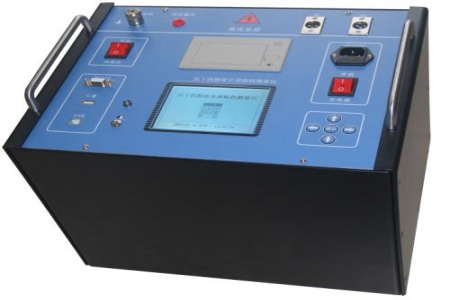
According to the measurement requirements of GB/T 14048.1 for switch contact resistance, on-site maintenance often uses 100A or 200A DC current for loop resistance testing to verify the contact state of the contacts. The following Q&A addresses common issues in the practical use of DC resistance testers.
A: The device supports two power supply modes: DC 11V–14V and AC 220V. The internal power management module can maintain stable output during voltage fluctuations. When on-site power access is difficult, it can be directly connected to the DC panel or battery bank for power supply, avoiding interruption of testing due to power supply problems. The recommended operating ambient temperature is 15–25°C, and the relative humidity should not exceed 85%, to ensure the repeatability of resistance measurement values.
A: For the low-resistance range of 1μΩ–200mΩ, the instrument uses a four-wire Kelvin connection method to eliminate the influence of lead resistance and contact resistance. Before testing, calibration with a standard resistor is required, and the current terminals and voltage terminals must be connected separately. When measuring switch contact resistance on site, it is recommended to perform the measurement with the contacts clean and free of oxide layers, and to take the average of multiple measurements to reduce dispersion.
A: Inductive loads such as transformer windings and reactors generate back EMF at the moment the test current is interrupted. The instrument has a built-in discharge circuit that automatically discharges the load after the test is completed, and the panel indicator shows the discharge status. Maintenance personnel must wait for discharge to complete before removing the wiring, and it is strictly prohibited to directly disconnect the current circuit during testing.
A: These dimensions correspond to a total weight of approximately 12kg. The housing uses an engineering plastic protective structure, suitable for short-distance transport within substations. The panel layout separates the power switch, current output terminals, and voltage measurement terminals into different areas, reducing wiring errors. The screen uses a high-brightness LCD display and is readable under strong light.
A: After each use, clean the test line clamps and check the clamp jaws for oxidation; during long-term storage, keep the environment dry to avoid moisture affecting the internal circuits due to excessive humidity. It is recommended to perform a standard resistor comparison every six months to confirm that the measurement deviation is within the allowable range. If the instrument shows fluctuating readings or fails to discharge, stop using it and return it to the factory for repair.

