

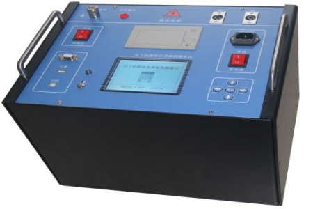
During transformer maintenance or switchgear handover on site, procurement personnel often need to answer one question: can this instrument accurately measure contact resistance at the 1 mΩ level under strong electromagnetic interference? The DRD-40B DC resistance tester is designed precisely for such on-site resistance measurement needs, using microprocessor control and a four-wire measurement method, and is suitable for DC resistance testing of low-resistance circuits such as transformer windings, switch contacts, and busbar joints.
The instrument can be used for DC resistance measurement of transformer windings, contact resistance measurement of circuit breaker conductive circuits, connection resistance inspection of busbars and cable joints, and also for low-resistance DC resistance testing of motor windings, transformer windings, and the like. The four-wire connection method can reduce the influence of lead resistance and contact resistance on measurement results, making it suitable for procurement personnel to arrange for use in equipment acceptance, preventive testing, and maintenance stages.
The measurement range covers 1 mΩ to 20 kΩ, with a resolution of up to 1 μΩ. The basic accuracy is calibrated in segments according to the range, and the specific values are subject to the accompanying technical manual. The instrument has a built-in constant current source and can automatically switch test current gears according to the measured resistance, reducing manual gear selection and making it convenient for on-site personnel to complete records item by item according to work instructions.
It is recommended to check the length and diameter of the test leads, the power supply method (AC power supply or built-in battery), display and storage functions, data export interface, and the accompanying calibration documentation. If used for transformer winding measurement, attention should also be paid to whether the instrument has an auxiliary winding temperature conversion function, so that measured values can be converted to a reference temperature in accordance with standard requirements.
Before measurement, confirm that the equipment under test has been powered off and fully discharged. During testing, the test circuit must not be disconnected arbitrarily. After measuring inductive windings, wait for the instrument to complete discharge before disconnecting the leads. The instrument should be stored in a dry environment, and the test lead connectors should be kept clean to ensure repeatability of low-resistance measurements.

