

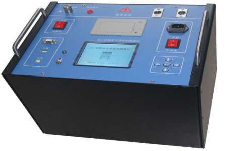
Design and selection personnel often encounter abnormal noises from switchgear or GIS equipment at substation sites, but conventional electrical tests do not reveal obvious problems. Such situations often require partial discharge detection, and whether the instrument can provide stable readings under strong electromagnetic interference is key to selection. The following is a Q&A format explanation focusing on the maintenance and precautions of partial discharge testers.
A: The pulse generator provides output charge ranges such as 5pC, 10pC, 20pC, and 50pC for calibrating the test circuit. During maintenance, the actual output corresponding to each range should be checked regularly to avoid deviations caused by capacitor aging or poor contact. Before each use, confirm the polarity and zero mark position to ensure that the calibration pulse and the test object's discharge signal are consistent in phase. The instrument has an internal automatic overload protection device. If the output terminal is accidentally short-circuited or overloaded, after the protection operates, the fault must be eliminated before restarting; do not force a reset.
A: Partial discharge testers often use elliptical scanning to display discharge waveforms. One maintenance point is to make the zero mark match all elliptical scanning frequencies; otherwise, the phase distribution of discharge pulses will shift. If the zero mark and scanning frequency are found to be inconsistent, check the synchronous power supply circuit and voltage divider connections to confirm that the reference voltage signal is stable. At substation sites, it is recommended to reliably ground the instrument's grounding terminal nearby to reduce interference introduced by ground potential differences. If stable synchronization still cannot be achieved, try changing the scanning frequency range to avoid the main interference frequency bands.
A: The discharge magnitude of test objects at different voltage levels varies greatly. When selecting, confirm that the instrument range covers the expected measurement range and pay attention to the response time of the automatic overload protection device. The protection function can reduce the risk of damage caused by misoperation, but it should not be used as a routine means of range switching. It is recommended to select the corresponding coupling unit according to the type of test object (such as transformer, GIS, cable) and verify whether the pulse generator's charge ranges meet calibration requirements. For occasions requiring long-term online monitoring, the zero drift of the instrument under continuous operation should also be examined.
A: The instrument should be stored in a dry, ventilated environment free of corrosive gases, avoiding severe vibration and direct sunlight. After long-distance transportation, it is recommended to first power on and preheat the instrument and check whether the output of each range is normal before putting it into on-site use. Coupling capacitors and connecting cables should be packaged separately to prevent connector deformation from stress. When not in use for a long time, power it on periodically for inspection to keep the internal capacitors in good condition.

