

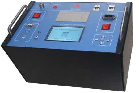
When purchasing a partial discharge tester, questions often arise regarding sensitivity, number of channels, anti-interference capability, and data repeatability. For example, is the measured discharge amount on site 5 pC or 50 pC? Why do results differ across frequency bands? The following outlines several reference points based on technical parameters and usage scenarios.
Partial discharge testers are typically based on the pulse current method or the ultrasonic method. Taking the pulse current method as an example, its measurable discharge range can reach 1 pC to 10000 pC, with a frequency band covering 10 kHz to 1 MHz. The polarity alternates between positive and negative, the repetition frequency can be set to 1.2 kHz, and the frequency variation range exceeds the required value, making it easier to distinguish interference from real discharge. Three-channel or single-channel configurations affect synchronization and localization capabilities; multi-channel is suitable for complex structures such as transformers and GIS.
This instrument can be used for partial discharge detection of transformers, GIS, high-voltage switchgear, cables, and instrument transformers. When purchasing, consider: whether it supports multiple pattern displays (PRPD, PRPS), whether it has digital filtering and windowing functions, and whether it provides a data export interface. For on-site inspections, it is recommended to choose a model with a built-in battery and a battery life of no less than 4 hours; for laboratory use, focus can be placed on analysis software functions.
Before testing, the square wave generator should be calibrated to ensure the gain and attenuation settings are correct. When ambient humidity is greater than 80%, additional shielding measures are recommended. If abnormal discharge signals are found during measurement, cross-validation can be performed using ultrasonic or ultra-high frequency methods. The instrument should be sent for inspection regularly to maintain valid calibration.

