

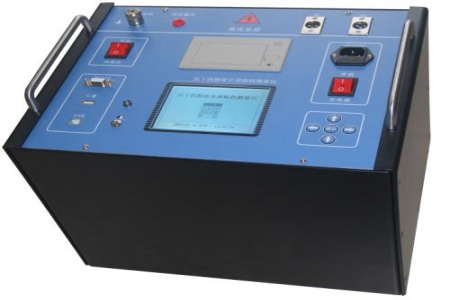
At the acceptance site of grounding grids for power plant booster stations, 500kV substations, or large industrial parks, grounding impedance testing often faces practical problems such as strong power frequency interference, large grid scale, and long wiring distances. When comparing different testing solutions, procurement personnel need to focus on the instrument's actual performance in terms of anti-interference capability, output current magnitude, measurement parameter coverage, and on-site operational convenience. The DRD-155A Large Grounding Grid Impedance Tester is designed for these scenarios and can be objectively compared with traditional power frequency high-current methods and variable-frequency low-current methods.
The traditional power frequency high-current method usually requires injecting tens of amperes of current to suppress interference, resulting in large equipment size, high power supply requirements, and complex on-site wiring. The DRD-155A adopts a variable-frequency measurement method with an output current of 5A, avoiding power frequency interference through frequency offset, thereby reducing power capacity requirements while ensuring measurement repeatability. For substations with large grounding grid areas and long wiring distances, this solution can reduce the transportation and wiring workload of test power supplies and voltage regulation equipment, making it suitable for projects with on-site efficiency requirements during procurement.
Clamp-on ground resistance testers are suitable for measuring small-scale grounding bodies such as tower grounding and independent grounding electrodes, but when used for large grounding grids, they are limited by loop impedance and wiring conditions and cannot fully reflect the overall characteristics of the grid. The DRD-155A can measure parameters such as grounding impedance, grounding resistance, grounding reactance, contact voltage, contact potential difference, step voltage, step potential difference, surface potential gradient in the field area, transfer potential, grounding down-conductor continuity resistance, and soil resistivity, covering the items listed in the new version of DL/T475-2006 "Guidelines for Measurement of Characteristic Parameters of Grounding Devices," making it suitable for procurement scenarios that require complete measurement of grounding characteristic parameters.
The instrument's measurement range covers 0.001Ω to 200Ω, with an output current of 5A and variable-frequency anti-interference capability, adapting to measurements in strong electromagnetic environments of substations. During procurement selection, comprehensive evaluation can be made based on grid scale, interference level, number of required measurement parameters, and on-site power supply conditions. Compared with variable-frequency low-current (3A and below) solutions, the 5A output provides a more ample signal-to-noise ratio under strong interference; compared with high-current solutions of 10A and above, the equipment weight and power supply requirements are lower, making it suitable for projects that need to balance measurement effectiveness and on-site portability.
The DRD-155A is suitable for handover acceptance, periodic testing, and characteristic parameter evaluation of grounding grids in power plants, substations, converter stations, large industrial parks, railway traction stations, etc. The instrument supports grounding down-conductor continuity resistance measurement and soil resistivity measurement, allowing multiple grounding characteristic tests to be completed with the same set of equipment, reducing the number of on-site equipment switches. For procurement personnel, specific configurations and accessory solutions can be confirmed with suppliers based on project grid area, interference source distribution, and measurement parameter list.

