

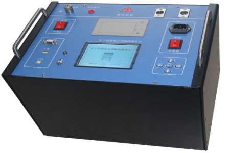
During substation ground grid testing, it is common to encounter significant differences in measured values at the same test point at different times, or noticeably high readings when near live lines. This is usually related to the layout of test circuit leads, interference voltage, and changes in soil moisture. The DRD-58C Large Ground Grid Tester is designed to address the above field problems. It adopts a variable-frequency measurement method, collecting data at two frequencies of 45Hz/55Hz and converting them to power-frequency impedance, which helps reduce the impact of power-frequency interference on readings.
The impedance measurement range covers the order of 0Ω~150mΩ, and the resolution meets the routine testing requirements for ground grid impedance and continuity resistance. The working power supply is 220V (within the allowable deviation range), adapting to on-site maintenance power conditions. The voltage line uses a copper-core conductor with a cross-sectional area of not less than 2.0mm², which helps reduce the additional error caused by lead resistance to the measurement results. The whole unit weighs about 5kg, making it easy for one person to carry to various test points in the site area, reducing the burden of transportation.
The instrument has a power-frequency interference suppression function. During measurement, it can display the interference voltage level, prompting the operator to judge whether the current test point environment is suitable for taking readings. The test current output is stable, and with the standardized layout of the voltage electrode and current electrode, it can complete measurements of ground grid grounding impedance, grounding continuity resistance, and other items. The data storage and query functions facilitate on-site recording and subsequent comparison.
It is suitable for grounding impedance testing of large grounding grids in power plants and substations, and can also be used for measuring the grounding resistance of independent grounding devices and towers. During on-site use, it is recommended to arrange the current electrode and voltage electrode according to regulatory requirements, and keep the leads away from strong interference sources as much as possible; if readings are abnormal, check the lead connections and soil conditions, and take stable values from multiple measurements. The instrument panel provides wiring diagrams and operation instructions, making it easy for operation and maintenance personnel to complete the test step by step.

