

Design and selection personnel often face a specific problem: substation grounding grids are large in area and soil conditions are complex. The traditional power-frequency high-current method requires laying long-distance current and voltage electrodes, resulting in high wiring labor intensity. In addition, power-frequency interference exists on site, leading to large dispersion and poor repeatability of measurement results. Especially in grounding grids where grounding impedance is inductive or resistive coupling is strong, how to obtain stable and comparable grounding impedance data without relying on a high-current loop has become a key factor to weigh during selection.
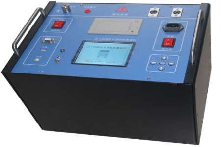
The DRD-40B large grounding grid impedance tester adopts a heterodyne multi-power method, with an output frequency deviating from the power frequency. Combined with software and hardware filtering technology, it improves anti-interference capability at substation sites where power-frequency interference exists. The instrument eliminates mutual inductance interference between measurement leads through computer data processing, ensuring measurement accuracy. Its wiring method does not require large-cross-section current lines, reducing on-site labor. The equipment has an output power range of 0–20 kW, an output voltage of 0–1000 V, and an output current of 0–50 A, and can adapt to the testing needs of grounding grids of different scales.
AC impedance measurement range: 0–999.9 Ω; the instrument adopts a Chinese LCD display, allowing direct reading of measurement results, and has a printing function; it is small in size and light in weight, facilitating on-site transportation and operation. Interference between measurement leads is handled by an internal algorithm, requiring no additional compensation.
This instrument is suitable for on-site measurement of parameters such as grounding impedance of large grounding grids, soil resistivity, and grounding grid conduction characteristics in power plants, substations, communication base stations, petrochemical sites, and other locations. For design and selection personnel, if the grounding grid area is large and power-frequency interference is obvious, the heterodyne multi-power scheme can be given priority; if the testing site has high requirements for wiring convenience, the instrument's wiring method can reduce the length and cross-sectional area of current electrode leads. During specific selection, please comprehensively evaluate based on the grounding grid diagonal length, soil resistivity range, and on-site interference spectrum.

