
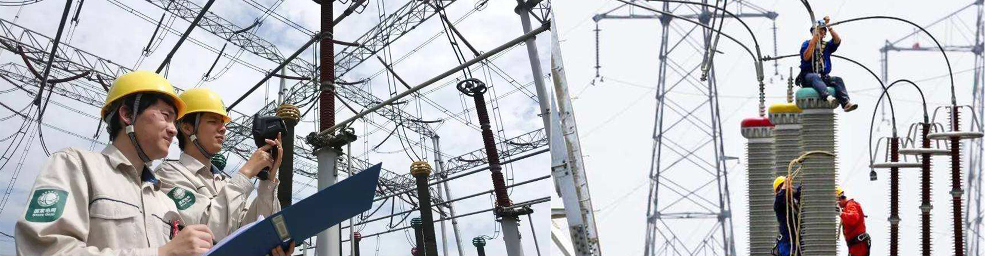
Partial discharge testing plays a crucial role in the maintenance of power systems. By detecting partial discharge signals early, the health of electrical equipment can be effectively assessed, preventing major failures. This article will detail the working principles, application scenarios, and importance of partial discharge testers in the power industry.
Introduction to Partial Discharge
Partial discharge refers to a non-continuous discharge phenomenon that occurs in localized areas of insulation in high-voltage power equipment when the electric field strength reaches a certain threshold. Although these discharges are relatively small in scale, their long-term presence can damage insulating materials, ultimately leading to equipment failure. Therefore, timely detection and location of partial discharges are crucial for the maintenance of power equipment.
Working Principle of Partial Discharge Tester
Partial discharge testers typically employ multiple techniques to detect partial discharge signals:
Radio Frequency Method (RF): Uses antennas to receive electromagnetic waves generated by partial discharges.
Ultrasonic Method (UHF): Detects ultrasonic signals caused by partial discharges.
Optical Method: Uses optical sensors to capture photons generated by partial discharges.
Chemical Method: Detects gas changes caused by partial discharges.
The tester collects various signals generated during partial discharge and analyzes them to determine the location, intensity, and type of discharge. Additionally, some advanced testers can provide three-dimensional location functions, helping maintenance personnel pinpoint problems more accurately.
Application Scenarios
Partial discharge testing is widely used in the detection of various high-voltage electrical equipment, including but not limited to:
Transformers: Detects partial discharges between windings or between the core and windings.
High-voltage cables: Identifies insulation defects at cable joints or terminations.
GIS (Gas Insulated Switchgear): Monitors partial discharges in SF6 gas.
Generators: Assesses the insulation condition of stator and rotor windings.
Test Steps
Preparation: Ensure the equipment under test is de-energized and properly grounded according to safety regulations.
Connecting Instruments: Select appropriate sensors based on the equipment type and install them in suitable locations.
Setting Parameters: Configure the tester's sensitivity, frequency range, and other parameters.
Executing the Test: Start the tester and record partial discharge signals.
Data Analysis: Analyze the recorded data to determine the extent and location of partial discharges.
Precautions
Before conducting partial discharge tests, carefully read the equipment manual to ensure all operations comply with manufacturer requirements.
During testing, pay attention to personal protection and avoid contact with high-voltage components.
Data analysis should be performed by professionals to accurately assess equipment condition.
Conclusion
Partial discharge testing is a key component of preventive maintenance for power equipment. By regularly detecting partial discharge activity, problems can be identified early, and appropriate maintenance measures can be taken, thereby extending equipment lifespan and reducing the risk of unexpected outages. With technological advancements, the functionality of partial discharge testers will become more comprehensive, providing stronger support for the safe operation of power systems.
This article provides readers with basic knowledge about partial discharge testers, covering their principles, applications, and operational guidelines, helping technical personnel in the power industry better understand and apply this important tool.

