

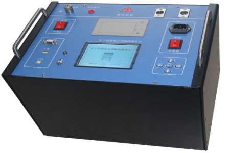
At the site of switchgear handover tests or preventive tests, design and selection personnel need to confirm whether the loop resistance tester can stably perform contact resistance measurement tasks over the long term. The ZHC-100S Loop Resistance Tester adopts the four-terminal measurement method, connecting to the device under test via dedicated test leads, with the voltage measurement leads connected inside the current output leads to reduce the influence of lead resistance on measurement results. The measurement accuracy is 0.5 class, making it suitable for handover tests and preventive test scenarios that require high consistency in contact resistance values.
When wiring, first connect the current output leads to both ends of the device under test, then connect the voltage measurement leads inside the current output leads, ensuring that the voltage clips and current clips do not overlap. After powering on, select an appropriate range and record the data once the reading stabilizes. Avoid moving the test leads during testing to prevent reading fluctuations caused by poor contact. After testing is complete, disconnect the current output first, then remove the voltage measurement leads, and coil the leads in the reverse order.
The instrument should be stored in a dry, ventilated environment free of corrosive gases, avoiding direct sunlight and severe vibration. When not in use for a long time, it is recommended to power it on once a month for about 30 minutes each time to keep the internal circuits dry. Test leads should be coiled naturally for storage, avoiding sharp bends or heavy pressure. Regularly check whether the lead clips are oxidized or loose, and replace them promptly if any abnormality is found.
During design and selection, it is recommended to first confirm the capacity range and testing frequency of the switch under test. The ZHC-100S has an output current of 100A, a measurement range of 0~1999μΩ, and a resolution of 1μΩ, meeting the contact resistance measurement needs of common switches. The operating power supply is AC220V±10%, 50Hz, adapting to most on-site power supply conditions. The instrument adopts a portable structure, making it easy to carry to different test locations.
Before testing, confirm that the device under test has been powered off and reliably grounded. Do not touch the current output terminals during testing. The instrument's grounding terminal should be reliably connected to earth. If strong electromagnetic interference exists on site, it is recommended to shorten the test leads or adopt shielding measures. After testing is complete, wait for the instrument to fully discharge before removing the wiring.

