

Design and selection personnel often directly choose the upper range limit based on the nameplate resistance value of the device under test, while ignoring the matching relationship between test current and resistance value. According to the basic principle of DC resistance testing, the instrument needs to apply a constant current to the load and collect voltage. If the current range does not match the measured resistance, a voltage signal that is too small is susceptible to interference, while one that is too large causes load heating. It is recommended to select the upper range limit at 1.2 to 1.5 times the measured resistance, and at the same time confirm whether the instrument's minimum resolution in the low-resistance section and maximum test current in the high-resistance section meet standard requirements.
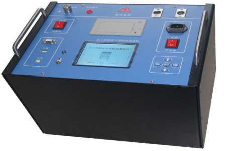
The winding or circuit resistance values of different devices vary greatly, and a corresponding relationship must be established during selection: transformer winding DC resistance is usually in the milliohm to ohm range, so 1A to 10A ranges should be selected; circuit breaker circuit resistance is mostly in the microohm range, requiring 20A to 100A ranges; busbar joints and switch contact resistance can refer to the same level. The ZDR-50B provides multiple ranges of constant current output, covering a measurement range of 0 to 20kΩ. During design and selection, the corresponding range can be selected according to the resistance interval of the actual measured object, avoiding mismatching large current with small resistance or small current with large resistance.
DC resistance measurement requires waiting for current stabilization and inductance decay. Transformer windings, especially large power transformers, have a large time constant, and measurement time may range from tens of seconds to several minutes. The ZDR-50B adopts a constant current source fast establishment and discharge circuit design, which can shorten the stabilization waiting time in typical transformer winding tests. During selection, it is necessary to confirm with the supplier the reference stabilization time values under different inductance levels and match them with the on-site power outage maintenance window.
There are power-frequency electromagnetic interference and residual magnetism effects at substation sites. If the instrument's common-mode rejection capability is insufficient, readings will fluctuate. Attention should be paid to the instrument's power-frequency interference resistance, input protection level, and grounding method. The ZDR-50B has input overvoltage protection and reverse electromotive force discharge circuits, which can reduce the impact on the instrument at the moment of power-off of inductive loads. During design and selection, test reports for electromagnetic compatibility test items can be requested as reference.
Some design and selection requirements require that test data can be exported to a production management system. The ZDR-50B is equipped with a USB or RS232 interface and supports data storage and upload. During selection, it is necessary to confirm whether the communication protocol is open, whether the host computer software supports common database formats, and whether it meets the access conditions for on-site laptops or tablet terminals.
On-site power supply conditions vary greatly. In some substations, the maintenance power supply is only single-phase AC 220V, and in some scenarios there is no mains electricity. The ZDR-50B supports AC power supply and can be optionally equipped with a built-in battery, with an operating temperature range of -10℃ to 50℃. During design and selection, the on-site power supply system, altitude, and protection level requirements should be verified to ensure that the instrument can start and measure normally in the expected environment.

