

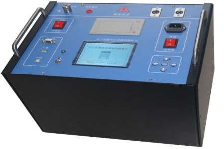
In on-site O&M, a specific problem is often encountered: when a grounding grid tester measures inside a substation, readings fluctuate repeatedly due to 50 Hz power-frequency interference, and results remain inconsistent even after switching to several measurement points. The problem often lies not in the measurement points themselves but in the way the instrument suppresses interference.
Some similar devices use single-frequency injection, so the measurement signal overlaps with on-site 50 Hz power-frequency interference in the frequency domain, requiring long averaging times or manual judgment to remove abnormal values. The DRD-160E uses multiple automatic dual-frequency modes such as 45 Hz/55 Hz and 49 Hz/51 Hz to separate the measurement signal from 50 Hz power-frequency interference in the frequency domain. Combined with hardware filtering, its ability to resist 50 Hz power-frequency voltage interference reaches 10 V. For O&M personnel, this means better reading stability when measuring near live operating environments and fewer repeated measurements.
Large grounding grid testing often requires multiple trips to the site, carrying different instruments to measure grounding impedance and potential gradient separately. The DRD-160E can measure parameters including grounding impedance, grounding resistance, grounding reactance, surface potential gradient in the site area, contact potential difference, contact voltage, step potential difference, step voltage, transfer potential, grounding down-conductor continuity resistance, and soil resistivity. One device covers the main items of large grounding grid testing, reducing on-site device switching and wiring adjustments. The impedance measurement range is on the order of 0 Ω to 150 mΩ, and the unit weighs approximately 5 kg, making it easy for one person to carry to various measurement points in the site area.
Before measurement, confirm the routing direction of the current electrode and voltage electrode, and avoid paths parallel to operating lines to reduce coupling interference. After each test, check the test lead connectors for oxidation or looseness, as connector contact condition directly affects the measurement loop impedance. For long-term storage, place the instrument in a dry environment and periodically power it on to check the display and button functions. In case of thunderstorms on site, stop testing and evacuate the site area; grounding test leads must not be connected to the grounding grid during thunderstorms.
The device is suitable for grounding grid parameter testing in substations, power plants, communication base stations, and large industrial site areas. It can also be used for comparative measurements before and after grounding renovation and for annual preventive tests. On-site O&M personnel can incorporate it into the routine tool configuration for grounding grid condition testing according to their organization's test cycle arrangements.

