

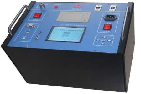
During grounding resistance testing of substation grounding grids, on-site O&M personnel frequently encounter situations such as insufficient spacing between current and voltage electrodes, significant interference, and poor repeatability of measurement results. The following Q&A addresses common questions regarding model selection and use.
Output capability must match the measurement range. Taking the DRD-95E as an example, the instrument has a maximum output current of 3A and a maximum output voltage of 400V, with a measurement range covering 0.001Ω to 200Ω. During on-site testing, an appropriate current gear should be selected based on the scale of the grounding grid and soil conditions, balancing test efficiency while ensuring signal-to-noise ratio. Stable current output helps improve reading consistency in the low-resistance range.
The metal parts of current and voltage stakes should be coated with anti-rust oil to reduce contact resistance and slow corrosion. When routing cables, avoid underground metal pipes and cable paths, and maintain sufficient spacing between the current electrode and voltage electrode to reduce mutual inductance effects. In dry soil, appropriate watering can improve conductivity, but readings should be taken only after the moisture has penetrated evenly.
First check whether the wiring is secure and the electrode contact is good, then confirm whether power-frequency interference or high-frequency noise is present. Variable-frequency measurement can be used to avoid interference frequency bands, and multiple measurements can be averaged. If fluctuations remain large, check whether the arrangement distance of the current and voltage electrodes meets the test requirements.
Regularly check the test leads for damage to the insulation layer, reapply anti-rust oil to the metal parts of the electrodes, and keep the instrument storage environment dry and ventilated. Before reuse after long-term shutdown, perform a power-on self-test and verify the measurement gear.

