

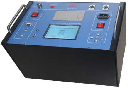
During the commissioning and maintenance of transformer on-load tap changers, incomplete transition waveform records, large dispersion of transition resistance values, and difficulty in judging three-phase simultaneity are commonly encountered. Design and selection personnel need to evaluate whether the tester meets field requirements from the perspectives of measurement principles, sampling capability, and signal processing methods.
The action process of an on-load tap changer is usually completed within tens of milliseconds. The tester needs a sufficiently high sampling rate to restore the details of transition resistance connection and disconnection. The DRD-8500 uses six independent signal processing channels, combined with a high-speed A/D conversion circuit, with a sampling rate of 10 kHz, and can record the time nodes of resistance changes during the transition process, providing raw data for transition time calculation.
There is a time difference in the action of three-phase tap changers. This instrument separately collects the transition resistance signals of phases A, B, and C, compares the start and end moments of each phase waveform on the same time base, and calculates the three-phase simultaneity deviation. The measurement circuit is designed for the transition resistance range of on-load tap changers and can adapt to signal acquisition in different resistance value ranges.
Transition resistance is a current-limiting element, and its resistance change is reflected in the transition waveform. The instrument converts the resistance signal into a voltage signal through the measurement circuit, and after A/D conversion, it is processed by a computer to read the resistance value during the transition process. This method is suitable for transition resistance measurement scenarios of conventional on-load tap changers.
It is recommended to compare from dimensions such as sampling rate, number of signal channels, transition time measurement range, transition resistance measurement range, and synchronization measurement error. The DRD-8500 provides six independent channels and a 10 kHz sampling rate, and its waveform display and data storage functions facilitate subsequent analysis. During selection, a comprehensive judgment should be made based on the model of the tested switch, the nominal value of the transition resistance, and on-site wiring conditions.

